
Reid & Mitchell (R&M) recently converted for the first time ever a dragline’s motor generator (MG) set from 60Hz to 50Hz operation.
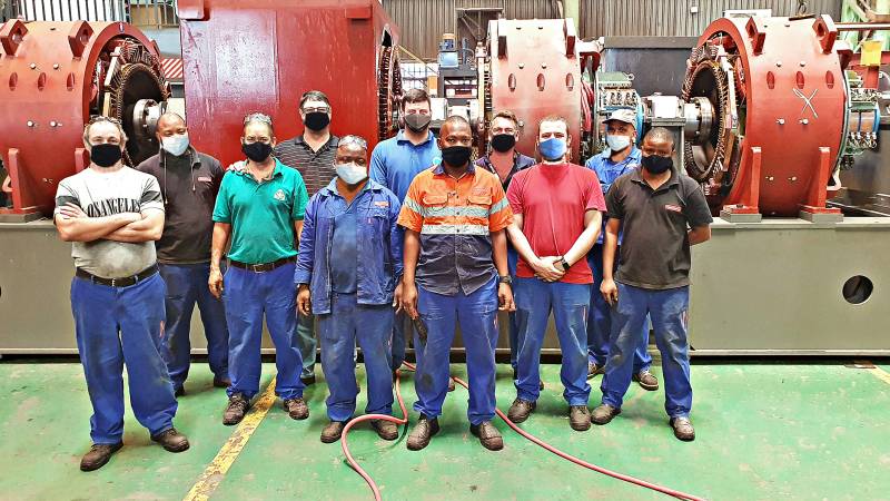
R&M’s test and assembly teams are shown above standing in front of the first motor generator (MG) set converted from 60Hz to 50Hz, with three more MG set conversions to follow in coming months. Among them are Willie Liebenberg, R&M’s Technical Executive (fourth from left); Shaun Dengler, Test Bay Foreman (fourth from right); and Albert Sibisi, DC Motors and Generators Foreman (second from right), who headed the assembly team.
The complex project involved extensive redesigning and remanufacturing of components to meet the new requirement. The dragline, originally designed and manufactured to operate in North America, where the national grid operates at 60Hz, has been sold to an opencast mine in North Africa, resulting in its MG sets having to be converted to 50Hz operation, as per the normal African grid frequency.
The conversion contract, commenced in October last year and due to be completed in November this year, involves the conversion of a total of four Ward Leonard MG sets, comprising total items of equipment as follows:
l Two 2000HP synchronous motors
l Two 3000HP synchronous motors
l Ten 1045kW generators
l Four 836kW generators
l 22 pedestals with white-metal bearings
“All of these items have to be comprehensively altered to meet the new specifications. With our completion and successful testing recently of the first converted set of the four MG sets requiring conversion we have overcome the bulk of the challenges we faced initially due to a lot of the work involved being new to us at that stage,” commented Willie Liebenberg, R&M’s Technical Executive.
“Converting the first set involved dealing with new challenges, but having gained that experience we now expect to carry out the other three conversions more easily and speedily than with the first,” he added.
The conversion involves:
l Redesigning and manufacturing a new rotor and stator for the AC synchronous motor, including installing new coils on both.
l With the DC generators only the frames of the original units were retained, while the replacement armatures had to be manufactured to new designs – one design for the three 1045kW generators and another for the 836kW generators – while the coil designs of the new units also differ from the original 60Hz versions. As with the new rotor and stator for the synchronous motor, the new components for the generators are manufactured inhouse by R&M.
“The challenge was to design the generators to produce the same output at a slower speed than what the 60Hz generators used to operate at. The main constraint is that the frame sizes of the 50 and 60Hz frames are significantly different from each other,” said Willie.
The 60Hz frame is in fact smaller in diameter and shorter in length than the standard 50Hz frame. This means having to redesign the 50Hz coils to fit into a smaller and shorter frame than normal, while at the same time designing and manufacturing a bigger armature than normal to reduce the air gap between the coils and the armature to meet the necessary flux requirements,” he explained.
To achieve the right combination of coil design and armature the new coils had to be made thinner and longer than the normal 50Hz coils, resulting in the coils projecting outside the frame.
Four different tests have to be carried out on the converted generators, which are:
l A saturation test.
l A short circuit test.
l A partial load test.
l A full load back-to-back test.
Because it is a new generator design, there is an additional special design test – known as the “black band” test – that also has to be carried out on one of the four generators after completion of the conversions to confirm that the generators have been converted correctly.
The conversion of the first of the four SG sets covered by the current contract was successfully completed in mid-March this year and dispatched a few days later to North Africa for installation on the dragline.
Fine-tuning DC commutation by ‘black band’ method
The aim of the “black band” test carried out at Reid & Mitchell (R&M) recently on one of the generators in an MG set it has converted from 60Hz to 50Hz operation was to fine-tune the DC rotating equipment to its optimum commutating condition.
“It is a method of commutation adjustment that involves intentionally misadjusting the magnetic strength of Inter Poles (commutating field) by adding or subtracting current to find the limits of sparking. This data is also used to adjust neutral setting and IP shimming to effect good commutation over the range of speeds and loads,” explained Willie Liebenberg, R&M’s Technical Executive, who conducted the “black band” test at R&M’s Benoni facility after the division had converted the first of four MG sets for a dragline due to be deployed at an opencast mine in North Africa.
“It is the most accurate practical method of ensuring that the brush rigging is in the proper position, and that commutating field strength is of the proper value for optimum commutation,” he added.
A “black band” test must be performed under controlled factory conditions and the testing must be done under conditions of steady load.
“For the test an 85kW exciter genset was set up as buck-boost power supply, producing low voltage, high current. The armature circuit was connected in parallel with the commutating field circuit of the generator being tested,” said Willie.
Two DC current meters with metering shunts were required to measure buck-boost current and generator load current. A power supply and a forward/reverse Variac was used to control the polarity and shunt field current of the exciter. “Polarities must be determined to know when the exciter is bucking (opposing) or boosting (increasing) current,” he pointed out.
Initially the generator was run at no-load (0%) and rated voltage. A small amount of current was introduced in the commutating field circuit from the exciter. This current was increased until a very slight sparking was observed. The value of the exciter value was recorded at this point. The exciter supply was then reversed and increased in the opposite direction until the same level of sparking was observed. The amount of current applied in both directions indicates the “band limit” at no-load. At this point the neutral position of the brushgear can be determined.
The generator was then operated at various loads (100% to 150%) during which sparking was observed with the application of buck and boost currents.
“The results were plotted on a set graph to determine the deviation direction of the black band, which refers to no sparking in the area between a set of two curves,” Willie stated.
The results from the test proved that no adjustments of brush rigging position or shimming of IP poles were required.
By Willie Liebenberg, Technical Executive Reid & Mitchell
![]()